Scope
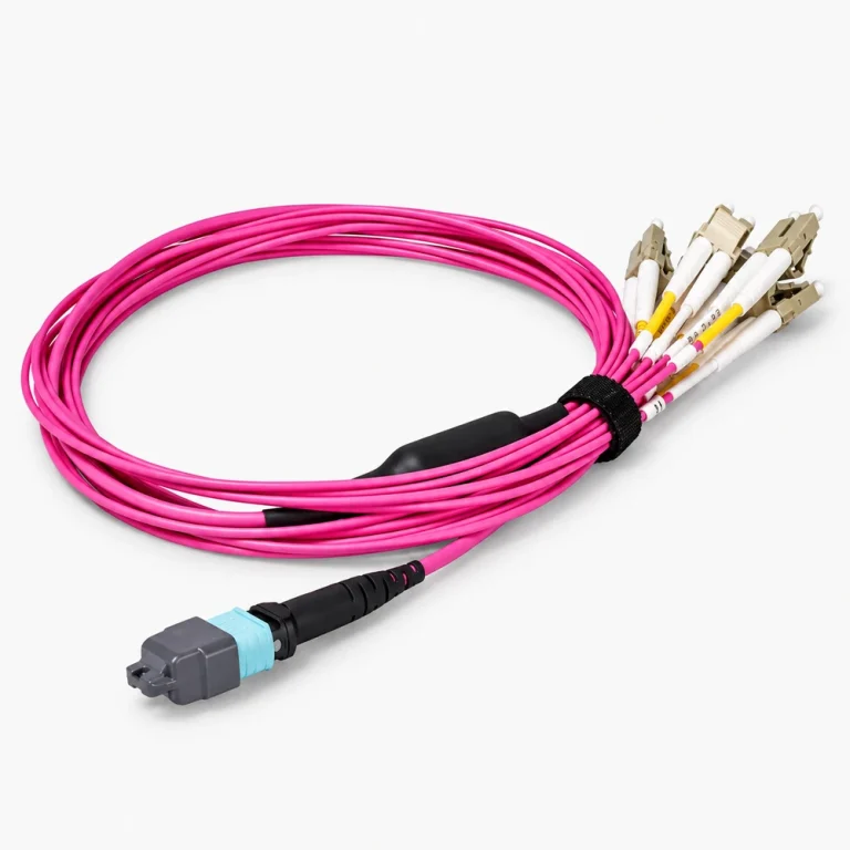
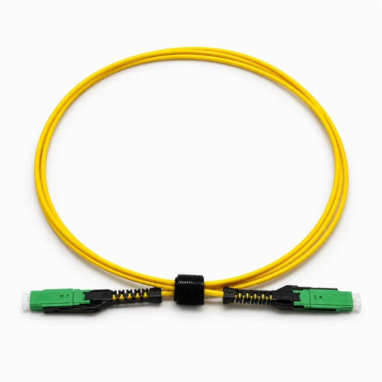
Patch cable requests should identify both connector ends, fiber type, polarity where relevant, construction, length, and deployment context.
Request preparation
Provide the complete end-to-end description, quantities by length, labeling or packaging needs, and destination requirements to be reviewed.
Technical parameters and selection boundaries
Published configurations differ by manufacturer and exact part number. These are selection dimensions, not one combined specification.
| Parameter | Documented example or choice | Verify for this request |
|---|---|---|
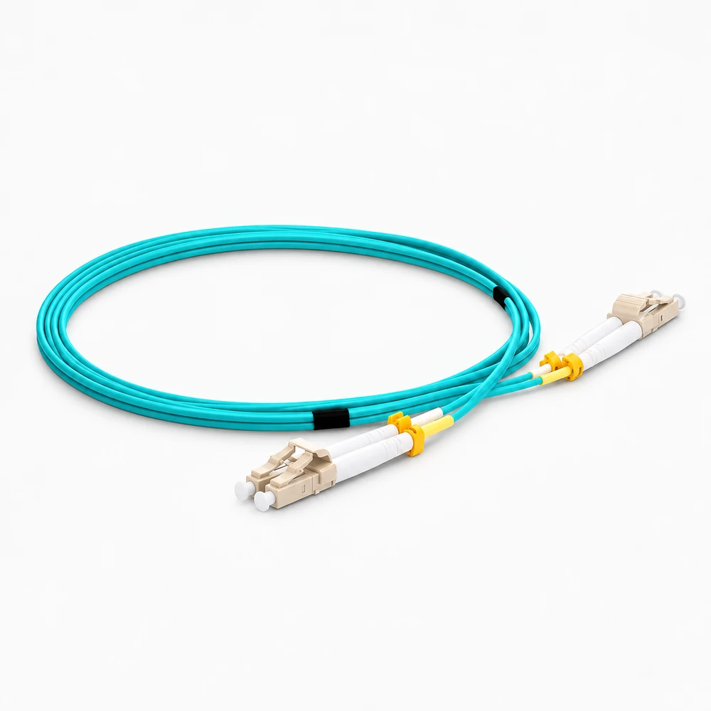
| Fiber and endpoint example | The reviewed TARLUZ configuration is an OM3 LC-to-LC patch cable. | Match the actual transceiver fiber requirement. OM3, OM4 and OS2 must not be treated as interchangeable labels. |
| Insertion loss | No more than 0.30 dB in this construction table. | Request wavelength, measurement method and per-assembly acceptance results. This is not a guaranteed complete channel loss. |
| Return loss | The OM3 specification table states N/A. | Do not import the separate general ordering table’s single-mode-style polish figures into this OM3 product. Require a measured value if the application needs one. |
| Connector ferrule | Zirconia ceramic in the named supplier range. | Ferrule material alone does not establish polish, end-face inspection or mating performance. |
| Cable diameter | 2.0 mm and 3.0 mm constructions appear in the specific OM3 table. | Select one finished diameter and check routing and strain relief. A generic ordering form elsewhere on the page is not evidence for every combination. |
| Jacket options | PVC, LSZH and OFNR are listed for the reviewed range. | Confirm the exact jacket construction and applicable fire requirements; these labels are not interchangeable approvals. |
| Temperature range | The supplier’s OM3 table lists −40 to +80 °C operating temperature. | Configuration-specific published value, not a universal OM3 cable or transceiver rating. Confirm the supplied assembly specification. |
Standard configurations and project options
| Configuration area | Documented option | Project decision |
|---|---|---|
| Standard and requested lengths | The table lists 1, 2, 5 and 10 m, or a requested length. | Provide route length, service slack and permitted finished-length tolerance. |
| Mechanical build | Choose the documented 2.0 or 3.0 mm construction and required jacket. | Do not combine optional features without a confirmed drawing or finished-part specification. |
| Optical acceptance | Specify the measured insertion loss, test wavelength, end-face cleanliness and polarity required for the channel. | The published loss figure does not replace inspection of the supplied assembly. |
Representative models and configurations
Examples illustrate real product variation. A listed manufacturer or model is not a statement of our stock, authorization, or confirmed availability.
| Manufacturer / series | Published configuration | Important scope |
|---|---|---|
| TARLUZ LC–LC OM3 configuration | LC at both ends; supplier-listed 2.0/3.0 mm constructions; 1/2/5/10 m or requested length. | Configuration example, not a complete manufacturer ordering code. Select one diameter, length, polish and jacket before requesting a quote. |
Applications and procurement context
- Use a patch assembly only after matching both optical interfaces, the installed fiber class, polarity, required length and channel loss budget. Specify replacement cables from the installed configuration rather than connector color alone.
Compatibility, current supply, lead time, origin, and acceptance documents must be confirmed for the actual order.