Scope
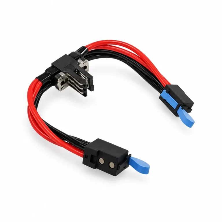
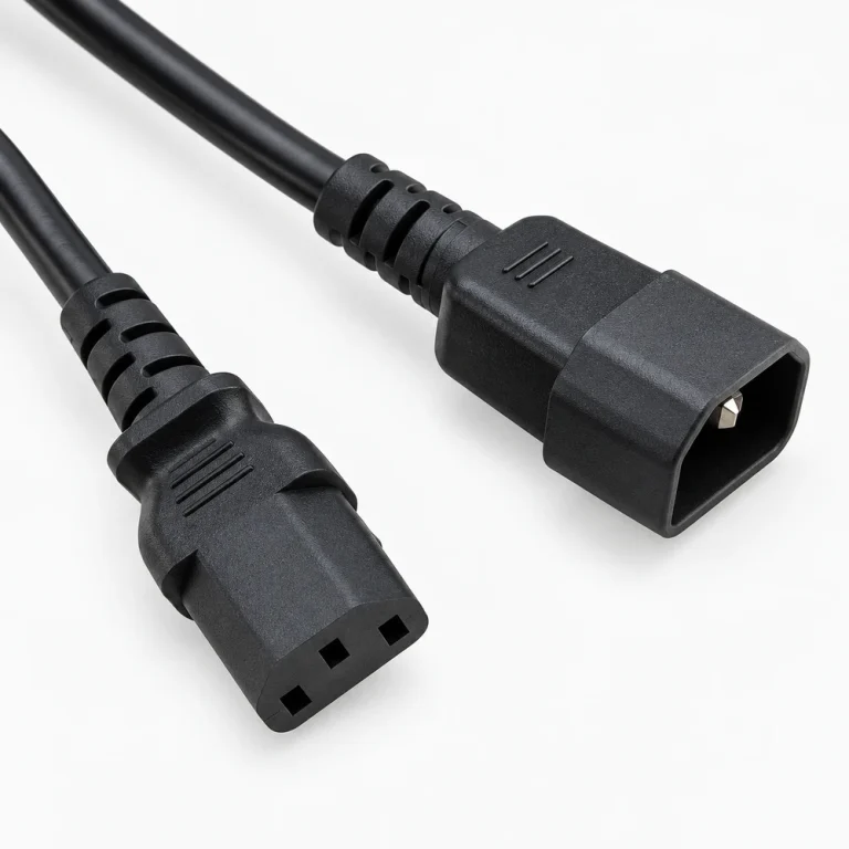
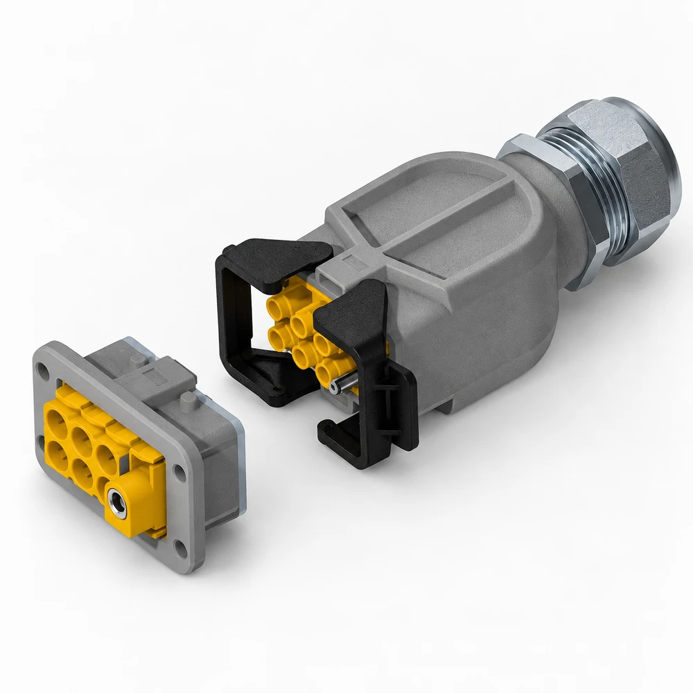
Power connector enquiries should distinguish housings, contacts, mating components, materials, ratings, and termination requirements.
Request preparation
Share manufacturer reference or complete series, housing and contact details, mating part, rating, material, termination, quantity, packaging, and destination requirements.
Technical parameters and selection boundaries
Published configurations differ by manufacturer and exact part number. These are selection dimensions, not one combined specification.
| Parameter | Documented example or choice | Verify for this request |
|---|---|---|
| Contact roles | The screw-mounted ORv3 IT-gear example separates dedicated chassis ground from a new sense contact. | Ground mates first and breaks last; sense mates last and breaks first. Verify the exact mating interface and contact sequence in the controlled drawing. |
| Panel movement | The IT-gear section specifies ±3.0 mm horizontal float. The BB1000 section separately specifies ±3 mm X/Y panel float. | Float allows defined alignment movement; it is not proof of compatibility with an arbitrary mating connector or cage. |
| Contact resistance and scope | The IT-gear feature list gives contact resistance below 0.55 mΩ. | The overview does not fully define the measurement method or exact ordering variant. Confirm those conditions in the selected connector specification. |
| Current must retain its conditions | The BB1000 feature box states 500 A load plus 500 A return at 300 LFM airflow and 45 °C. | Load and return are the circuit path; their sum must not be presented as a 1000 A usable circuit. Derating and assembly details require engineering confirmation. |
Standard configurations and project options
| Configuration area | Documented option | Project decision |
|---|---|---|
| Mounting and termination | BB1000 examples distinguish screw mounting with busbar/lugs from cable-attached termination. | Select the full connector and termination design together; confirm torque, conductor size, enclosure and mating-cycle requirements for the exact part. |
| Select by architecture and contact function | The IT-gear example is designed for 48 V architecture with ground and sense contacts. | Provide the voltage/current requirement, mating part, contact sequence and drawing. Do not choose only by a headline connector current. |
Representative models and configurations
Examples illustrate real product variation. A listed manufacturer or model is not a statement of our stock, authorization, or confirmed availability.
| Manufacturer / series | Published configuration | Important scope |
|---|---|---|
| TE ORv3 screw-mounted IT-gear connector | 48 V architecture; dedicated ground and sense; ±3.0 mm horizontal float. | Configuration description, not a verified complete MPN. The overview contains different current labels, so a universal current rating is deliberately not assigned. |
| TE BB1000 range | Dual-pole output connector with busbar/lug and cable-attached constructions. | The 500 A load / 500 A return feature requires its stated airflow and temperature conditions; no arbitrary assembly inherits this capability. |
Applications and procurement context
- Match a power connector to its exact rack/server architecture, mating part and termination. Preserve current derating, temperature, airflow, contact roles and mounting movement as separate procurement checks.
Compatibility, current supply, lead time, origin, and acceptance documents must be confirmed for the actual order.